— Systems

High power, high reliability
satellite electronic systems.

Spherical builds PCDUs, standalone modules, and specialised electronics for power conditioning, distribution, motion, propulsion, and fault-tolerant compute. PCDU configurations support up to 10 kW today, with higher-power systems on the roadmap. Inherently flexible with fault-protected digital configuration to modify voltages and current limits without hardware modifications.

Power1–10 kW
Radiationup to 100 krad / 62.5 MeV
Temperature−40 … +85 °C
BusCAN · RS-422
— 01 / PCDU

PCDU (Power Conditioning and Distribution Unit).

— K-series PCDU

The K-series PCDU is a modular power conditioning and distribution unit integrating solar-array regulation, battery interface, and protected load distribution in a single envelope. Each major function — SAR, battery, distribution — is a discrete module built from a common technical library; add or remove modules to match the mission, without redesign.

Digital by design. Regulator loops, secondary rail voltages, LCL trip currents and timing, and battery charge profiles are all digitally configured — at order, during AIVT, or in flight. Fault tolerance is built in: triple-modular redundancy on critical digital decisions, redundant control nodes, and analogue back-stops that protect the hardware if the digital layer fails.

Fig. 01K-series PCDU housing.
01.1 SAR — Solar Array Regulator MPPT / DET

High-power true Maximum Power Point Tracker (MPPT) with digital control. Designed to support high-current silicon cells for the most demanding high-power missions, with 1.5 kW per module. Resilience built-in with a redundant DET (Direct Energy Transfer) bypass path and dual-redundant ideal diodes. Full telemetry — all voltages, currents, and temperatures available over dual-redundant digital TMTC networks.

ParameterValue
Channel power500 W
Channels / module3
Max. voltage100 V
Efficiency95 %
01.2 PDM — Power Distribution Module Up to 12 rails · LCL-protected

Regulated and unregulated load channels from a single module. Up to 12 regulated outputs across configurable rails — 3.3, 5, 12, 28, or 50 V — each protected by a latching current limiter. Trip current, current-limit time, retry behaviour, and retry period are all digitally programmable per channel; configuration supports compliance with ECSS-E-ST-20-20C. Dedicated drivers for heater loads and Hold-Down Release Mechanisms (single-LCL or two-barrier arm/fire).

ParameterValue
Regulated outputsup to 12
Configurable rails3.3 / 5 / 12 / 28 / 50 V
LCL trip current0.2 – 10 A
Current-limit time0.5 – 20 ms
Retry period0.2 – 10 s
01.3 CIM — Common Interface Module CAN · RS-422 · redundant A/B

External command and telemetry interface to the spacecraft. CAN is the primary host bus; RS-422 / RS-485 is available for differential serial or legacy protocols. Both are exposed as fully redundant A/B channels so a single-point failure cannot silence the PCDU. Internally, modules talk to one another over a redundant digital bus with deterministic messaging — control loops, telemetry, and protection share a common timing reference. TM/TC covers LCL configuration, secondary-converter setpoints, telemetry streaming for battery / SARs / modules / temperatures, and event and fault logging.

ParameterValue
External I/FCAN · RS-422 / RS-485
Redundancydual A / B
Internal busredundant, deterministic
SEU mitigationTMR control nodes
01.4 PDE — Propulsion Drive Electronics Hit & Hold · latching · GaN

Drive, protection, and sensing for cold-gas, monopropellant, and electrothermal propulsion. Hit & Hold and latching solenoid valves are driven through GaN-FET H-bridges with closed-loop current control; tank heaters, nominal and redundant thruster heaters, pressure sensors, Type-K thermocouples, and NTC thermistors all share the same channel architecture. Every output is gated by a digitally configurable LCL — trip currents, hit/hold timing, and drive parameters are programmable per channel. Control runs on an FPGA hosted on a pluggable Mezzanine Board; the spacecraft DPU issues telecommands over SPI and reads back telemetry on the same link. Algorithms live on the DPU — the PDE actuates.

ParameterValue
Propulsion typescold-gas · monoprop · electrothermal
Valve driveGaN H-bridge (H&H + latching)
Sensor inputspressure · Type-K T/C · NTC
Channel protectionper-channel LCL, programmable
01.5 MOT — Motor Controller 2-phase stepper · resolver

Drive electronics for spacecraft mechanism and propulsion-actuator motors. Two-phase stepper drive with per-winding PI current control. Resolver feedback closes the position loop; a mass-flow sensor input closes the outer loop for propellant control. Four selectable schemes — open- and closed-loop position, each available standalone or layered under a mass-flow controller — run on the same hardware for characterisation, pointing, and propellant metering.

ParameterValue
Drive2-phase stepper, PI current loop
Position feedbackresolver
Sensor inputsthermocouple · mass-flow
Control schemesopen / closed position · mass-flow
Supply28 VDC, LCL-protected
— 02 / Standalone modules

Standalone modules.

For missions that don't need the full PCDU, Spherical supplies four standalone modules — power conversion, motor control, and fault-tolerant compute — as individually-buyable units. Same flight-qualification standard, same engineering team, scoped to the single capability the spacecraft needs.

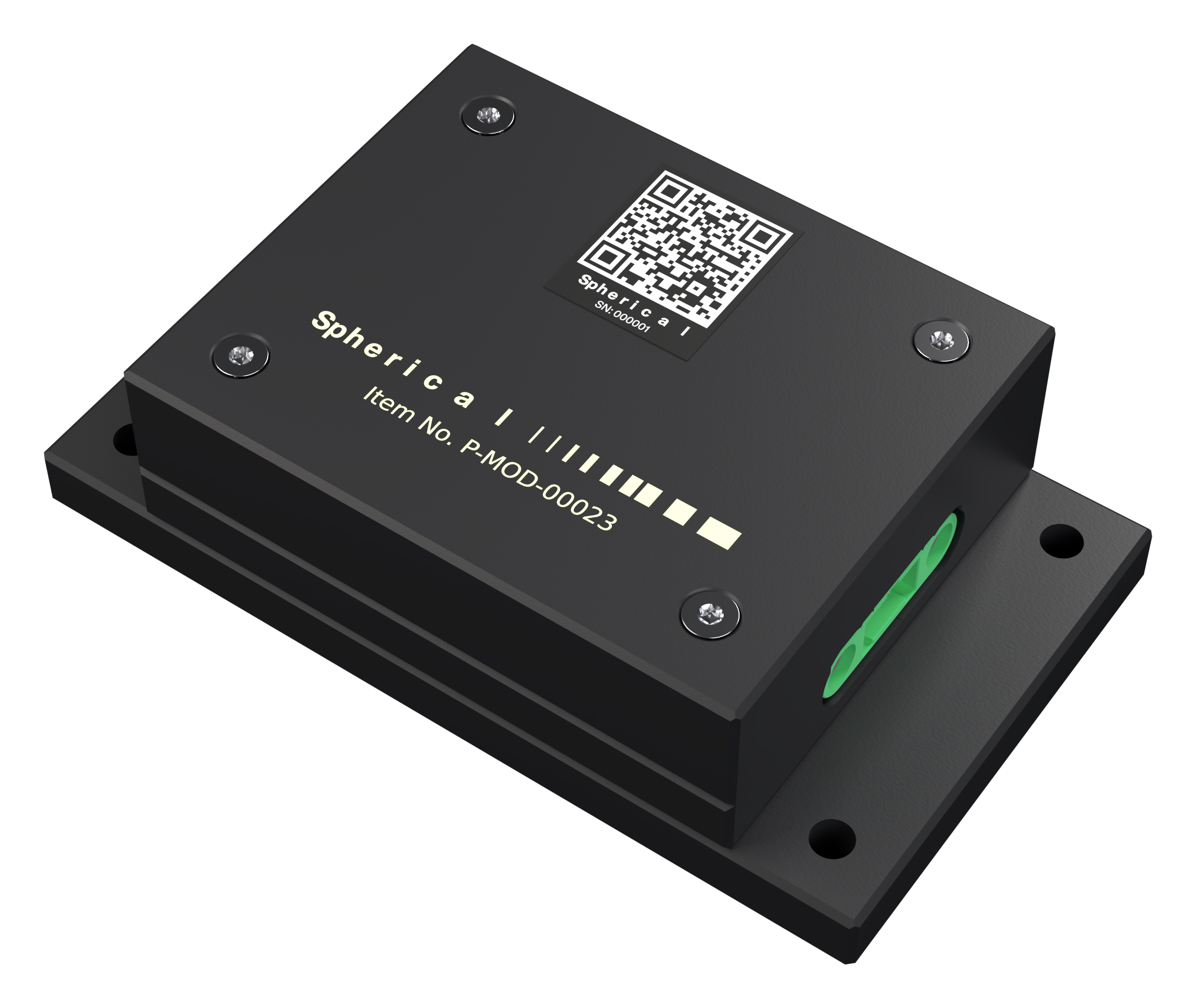
P-MOD-00023 flight module, isometric render.
Fig. 02P-MOD-00023 — flight unit.
02.1 ISO-100 DC/DC Converter dev

Compact isolated 100 W rad-hard converter for small-spacecraft buses.

  • Rated 100 W continuous at 92 % efficiency.
  • Wide input range, 22 … 34 VDC.
  • Switching at 500 kHz with planar magnetics.
  • Total ionising dose ≥ 100 krad(Si).
  • Operating range −40 … +105 °C.
  • Two-part aluminium housing, 71 × 41 × 21 mm.
02.2 POW-100 DC/DC Converter dev

Compact 100 W rad-hard converter for small-spacecraft buses.

  • Rated 100 W continuous at 92 % target efficiency.
  • Wide input range, 22 … 34 VDC.
  • Switching at 500 kHz with planar magnetics.
  • Total ionising dose ≥ 100 krad(Si).
  • Operating range −40 … +85 °C.
  • Two-part aluminium housing, 71 × 41 × 21 mm.
02.3 ISO-250 DC/DC Converter concept

250 W isolated DC/DC converter for space-grade buses.

02.4 MCU Fault-Tolerant Microcontroller concept

Fault-tolerant microcontroller module with integrated sensor front-ends.

02.5 MOT Motor Controller concept

Stepper and 3-phase BLDC motor controller with sensor feedback.

02.6 POW-250 DC/DC Converter concept

250 W non-isolated DC/DC converter for space-grade buses.

— 03 / Qualification

Test as you fly. Fly as you test.

Fig. 03TID exposure at the LANL Ion Beam Facility.
Fig. 04Random vibration to the NASA-GEVS envelope.
Fig. 05PD-220 in thermal-vacuum chamber, −40 °C cycle.
A.

Radiation

TID at LANL Ion Beam Facility. SEE characterised at heavy-ion and proton facilities. Reports delivered against ECSS-Q-ST-60-15C.

B.

Thermal vacuum

−40 … +85 °C cycling under 10⁻⁶ mbar, 8 cycles minimum per ECSS-E-ST-10-03C. Dwell at extremes for 6 hours.

C.

Vibration & shock

Random and sine to NASA-GEVS launcher envelope. Pyroshock to 4500 g per SRS.

D.

Documentation

One PO yields one ICD, one DDP, one acceptance data package. Configuration controlled, signed, delivered against the programme schedule.

— Procurement

Need the spec sheet, ICD, or a non-disclosure agreement?

Request data pack Silicon →